Severe metallization corrosion
Published:
Degradations induced from water ingress have the potential to trigger critical levels of corrosion which have been demonstrated to decrease the module maximum power by 80% in the worst-case during damp-heat tests [1].

This blog post investigates the effects of corrosion in photovoltaic modules. It starts by giving an overview and describing the mechanisms. Then, the electrical signature is presented as well as the interactions with other anomalies. Detection methods are briefly listed, and prevention considerations are discussed.
I. Overview and Mechanisms
Corrosion in PV modules can occur in various forms, starting with water and oxygen penetrating into the module [4].
On one hand, corrosion losses which affect the PV module transmittance (glass, antireflection coating) are fairly limited with a maximum impact of 4% [5]. Exceptions with larger losses might occur with high levels of soiling within, for instance, desertic environments [6].
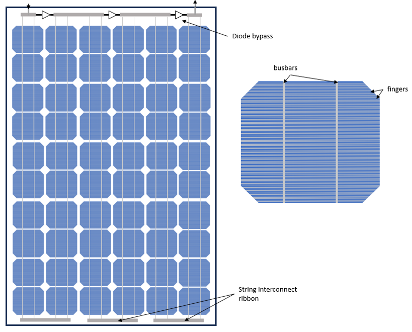
On the other hand, corrosion of the metallization attacks the cell busbars and ribbons on the PV panel shown in Figure 2.

Small levels of glass and metallization corrosion are expected over the PV module lifetime and are normally taken into account within module guarantees. However, advanced metallization corrosion levels might dramatically degrade module characteristics in the late stages of the nominal service life [3] decreasing the maximum power under 80% of the initial level specified in the datasheet.
Metallization corrosion is triggered from the release of acid acetic which is produced from the encapsulant (usually EVA) through hydrolysis reaction in the presence of heat and water. Then, the encapsulant ability to retain water ingress and sensitivity to heat are key factors to apprehend corrosion levels [3], [7], [8]. UV stress was also considered as a potential factor facilitating acetic acid production [9]. Backsheet properties and delamination might also accelerate this process by letting the water progress into the PV material sandwich [3].
II. Signatures
Critical corrosion degradation commonly occurs at the end of module life and significantly reduces PV panel performance. Figure 3 shows the IV characteristics of base c-Si PV cells undergoing prolonged exposure to hygrothermal vapors over saturated potassium chloride (KCl) solution containing 3% of acid acetic (HAc) with fixed temperatures in the [65-85°C] range [3].

A first decrease of Pmax comes from a reduction by the Fill Factor (FF) followed by a decrease of short-circuit current (Isc) which leads to very low levels of Pmax down to 0.5 of the initial value for the best case. On the other hand, the open-circuit voltage (Voc) has been proved to remain the same [3], [8].
The degradation processes have been modelled according to a sigmoid function as in equation (1) where $P_{sat}$ is the asymptotic limit, $t_0$ is the period and $s$ is the slope factor [1].
\[P(t) = P_{sat} + \frac{(1 - P_{sat})}{1 + \exp (\frac{t - t_0}{s})}\]Kontges et al. [3] further explain that the degradation can be broken down into two phases as shown in Figure 4.
- The first phase corresponds to the gradual decrease of the metallic connection under the metal grid which creates gaps between the fingers and the emitter surface to the point where the contact area is limited to silver (Ag) pillars [3]. This especially can be modeled by an increase in serial resistance (Rs) [8], [10].
- The second phase corresponds to the change of electrical properties of those Ag pillar contacts which decreases the short-circuit current (Isc) [3].

These two degradations seem to be independent of each other [3]. Inflection times from the same degradation process (Isc of FF) are linked according to the Arrhenius law as in equation (2) with their estimated activation energy $E_a$ [3], [8]. $t_1$, $t_2$ are two different inflection times of the process associated with two different temperatures $T_1$, $T_2$ and $k_B$ is the Boltzmann constant.
\[\frac{t_2}{t_1} = exp[-\frac{E_a}{k_B} \cdot (\frac{1}{T_2} - \frac{1}{T_1})]\]The activation energies for FF-reduction have been estimated in the range of [0.41 - 0.51eV] [3] while the Isc-reduction energy is in the range of [0.54 - 0.7 eV] [3].
At the end of the process, the degradation reaches a saturation phase with stable IV-characteristics.
III. Concomitant Failures
Several anomalies usually occur around the corrosion process. Often triggered by delamination, the encapsulant degrades and presents some yellowing marks before fostering corrosion with the acetic acid release [6], [9]. Glass breakage also leads to water ingress and accelerates corrosion effects [5]. PID has also the potential to increase corrosion levels through its own mechanisms [4], [6].
Corrosion degradations are often spatially-anisotropic [3], [11] which would induce some mismatches and potential hotspots [7]. Distinctive mismatches might also trigger bypass diodes which would accelerate their ageing mechanisms with prolonged operations than expected. In addition, cell interconnections are then weaker due to corrosion [7] and some fatigue failures can consequentially occur with some brown marks.
IV. Detection
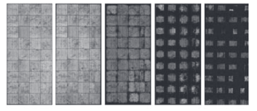
Corrosion can easily be recognized with visual inspections [4], [6]. Electroluminescence also reveals corrosion as in Figure 4. Given its IV-signatures with a decrease of Fill Factor (FF) due to an increase in serial resistance (Rs) and a decrease in short-circuit current (Isc), IV-tracing also becomes a way of identifying corrosion.

V. Tests & Prevention
Damp-heat tests are designed to determine the ability of the PV module to withstand long-term penetration of humidity. According to IEC 61215 [12], PV modules are exposed to a temperature of 85°C and a relative humidity 85% for 1000 h in the climatic chamber. If the maximum output power decreases by more than 5%, the test fails.
Some other ammonia tests according to the IEC 62716 [13] further assess the module resistance to corrosion. Given that ammonia has a relatively high corrosive effect, this test serves as a complement to the previously described damp-heat test.
Poor manufacturing processes with imperfect soldering or the choice of poor materials [6] facilitate corrosion. Environmental factors can also accelerate the corrosion (e.g. ammonia, salt, humidity, temperature) for PV installations which are located, for instance, next to the sea or in hot climates [4], [6].
Therefore, appropriate measures should be taken towards encapsulant of higher quality and better Water Vapor Transmission Rates (WVTR). One must note that bifacial glass modules have higher resistance to corrosion with typical lower WVTR. Limiting high temperatures within modules, when possible, would also extend the degradation of those. Avoiding cleaning modules with chemicals would also enable longer lifetimes.
References
[1] M. Koehl, S. Hoffmann, and S. Wiesmeier, ‘Evaluation of damp-heat testing of photovoltaic modules’, Prog. Photovolt. Res. Appl., vol. 25, no. 2, pp. 175–183, 2017, doi: 10.1002/pip.2842.
[2] H. E. Yang, R. French, and L. Bruckman, Durability and reliability of polymers and other materials in photovoltaic modules. William Andrew, 2019.
[3] M. Köntges, G. Oreski, U. Jahn, M. Herz, P. Hacke, and K.-A. Weiss, ‘Assessment of photovoltaic module failures in the field’, IEA PVPS, IEA-PVPS T13-09:2017, 2017.
[4] C. Miquel, C. Stravrou, N. Lebert, and J. Sarantou, ‘Dysfonctionnement électriques des installations photovoltaïques: points de vigilance.’, AQC - HESPUL, Technical Report PTVIGI1801, Oct. 2018.
[5] M. Köntges et al., ‘Review of Failures of Photovoltaic Modules’, IEA PVPS T13, Technical Report IEA-PVPS T13-01:2014, 2014.
[6] M. Herz, G. Friesen, U. Jahn, M. Köntges, S. Lindig, and D. Moser, ‘Quantification of Technical Risks in PV power Systems’, IEA PVPS, Technical Report IEA-PVPS T13-23:2021, Feb. 2022.
[7] M. Aghaei et al., ‘Review of degradation and failure phenomena in photovoltaic modules’, Renew. Sustain. Energy Rev., vol. 159, p. 112160, 2022, doi: 10.1016/j.rser.2022.112160.
[8] H. Gong, G. Wang, and M. Gao, ‘Degradation Mechanism Analysis of Damp Heat Aged PV Modules’, Jan. 2012, pp. 3518–3522. doi: 10.4229/27thEUPVSEC2012-4BV.3.38.
[9] Tsuyoshi Shioda, ‘Acetic acid production rate in EVA encapsulant and its influence on performance of PV modules’, Nov. 13, 2013.
[10] E. Sarquis Filho, ‘Toward a Predictive Strategy for the Operation and Maintenance of PV Systems’, PhD Thesis, 2023.
[11] J. Zhu et al., ‘Changes of solar cell parameters during damp-heat exposure’, Prog. Photovolt. Res. Appl., vol. 24, no. 10, pp. 1346–1358, 2016, doi: 10.1002/pip.2793.
[12] IEC, ‘IEC 61215: Terrestrial photovoltaic (PV) modules – Design qualification and type approval’. Mar. 2016.
[13] IEC, ‘IEC 62716 Photovoltaic (PV) modules - Ammonia corrosion testing’. May 2018.
