Bypass diode failure
Published:
Bypass diodes have a pivotal role in PV modules and their failures might lead to significant performance losses and even safety issues like fire or electric arcs.
This blog post gives an overview of bypass diodes and their failures with their root causes, signatures, and mitigation technics.
I. Overview
Bypass diodes in PV modules are used to handle important mismatch cases such as shading, cell crack, uneven soiling, etc… to prevent severe losses at the module level and high reverse voltages inducing hotspots at the cell level. Those are typically Schottky diodes which are commonly 3 (between 2 and 5 [1]) per PV module, each in parallel of a group of around 20 cells.
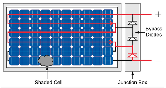
However, those diodes are subject to failure due to static high voltage discharges, mechanical and thermal stresses [3].
II. Root causes
The reasons for diode failures can appear at different stages:
- Manufacturing: wrong specification [4], non-functional diode, diode inversed at the assembling phase, wrongly-connected… [1]. Mechanical shock or electrostatic discharge during the PV module assembling phase might also trigger diode failures [1].
- Installation: Wrong installation (inversed or not properly connected [3]), mechanical stress on junction boxes, shocks… [1]
- Operation: Diode aging mechanisms, junction box corrosion, events with mechanical stresses [1] , electrostatic discharge and thermal runaways [5].
Electrostatic discharge occurs when a large current passes through the diode over a short period of time, which can occur, for instance, due to a lightning strike [5]. Thermal runaway occurs when the heat dissipation from a transition to another operation mode is too high to for the diode itself. [5], [6]
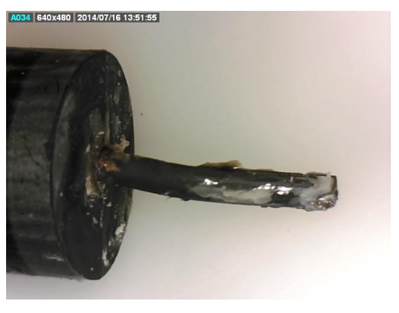
Note that when diodes are operating a higher number hours than expected, their lifetime decreases [1], [3] due, notably, to aging mechanisms and higher operating temperatures. For instance, in case of recurrent partial shading, bypass diodes might be operating more often, increasing the likelihood of diode failures [1], [3].
Bypass diode failures are functions of their operating temperature as introduced in several models such as the Semikron model [7] or the formula from the military MIL-HDBK-217 handbook [8]. The Semikron model notably captures thermal cycling to estimate the semiconductor lifetime while the MIL-HDB-217 enables to calculate the failure rate based on the operating temperature. For (low frequency) diode components, MIL-HDBK-217 [8] especially formulates the failure rate $\lambda $ in failure per million hours according to the following equation:
\[\lambda = \lambda_b \cdot \Pi_T \cdot \Pi_S \cdot \Pi_Q \cdot \Pi_E\]Where:
- $ \lambda_b $, the base failure rate: 0.0030 for Schottky diode.
- $ \Pi_T $, the temperature factor. For general purpose, with $T_j$ the component temperature, it can be expressed as \(\Pi_T = exp(-3091 \cdot (\frac{1}{T_j +273} - \frac{1}{298}))\).
- $ \Pi_S $ ,the electrical stress factor.
- $ \ Pi_Q $, the quality factor, equal to 5.5 for lower quality for instance.
- $ \Pi_E $, the environmental factor.
Then, those failures are more prone in hot climates [9]. Also, bypass diode failures are primarily revealed during the first ten years of the PV installation [1], [3]. Golnas highlights that bypass diodes are responsible for 3% of the PV module tickets over 350 PV systems operated by SunEdison [10].
III. Signatures & simultaneous failures
Failed diodes are either blocked in short-circuit or open-circuit [1], [3]. Short-circuited bypass diodes will constantly have a lower voltage capability and may shift the maximum power point of the entire PV array. On the other hand, open-circuited bypass diode might not reveal any power loss until a mismatch configuration within the PV module occurs.
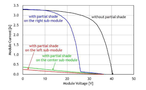
Several failures usually occur at the same time as bypass diode failures.
Causes
Partial shading has the potential to lead to hot-spots which can result in burn marks, bypass diode failures [3]. Other mismatches due to encapsulant discoloration, backsheet/frontsheet delamination, corrosion… might lead to the activation of bypass diode [3] which might then age prematurely. Also, the corrosion in junction box might weaken the bypass diode.
Concomittant
Cell hot spots might appear before, while the diode activate or after the diode failed.
Consequences
In case of failed open-circuited diode and mismatch, the current goes through the failed cell string and generates heat which might cause more severe hotspots and burnmarks. Then, very high temperatures or electric arcs may degrade even more the module integrity [3].
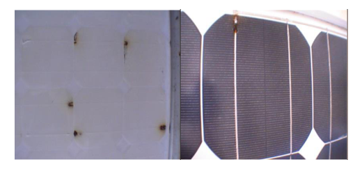
More dramatically, open-circuit diode might lead to electrical arcs and fires in some cases [1]. When bypass diode failures occur, the junction box might get affected and even burn [3]. Then, when the junction box or backsheet are burnt, the safety issues like leakage current may follow [3].
IV. Detection
Directly testing the diode with a multimeter in diode or ohmmeter mode is the best way to identify if the diode is short-circuited or open-circuited.
The open-circuit voltage measurement might reveal a failed diode that is short-circuited diode with a lower Voc than expected. Naturally, IV-curve with also capture this effect.
Infrared thermography might reveal some bypass diode activations or hotspots [3], [9]. During the activation of diode, higher temperature rise of the cell group is expected since the energy that is not converted to electricity will result in higher heat dissipation than the neighbor cells which generate currents.
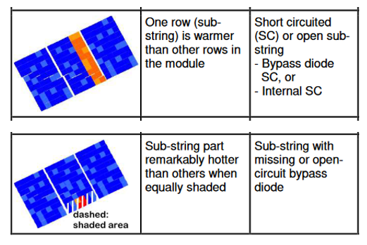
Open-circuit diode is more difficult to detect since no effect is perceivable if the module is not in a significant mismatch configuration [3], [11].
Recommendations
- In case of identified hotspots or burn marks, bypass diodes must be checked to make sure they activate to prevent more severe degradations [1], [9].
- Avoiding partial shading will extend the bypass lifetimes. [1]
Diode replacement is technically feasible [1]. However, replacing the whole module is usually what happens in practice. If not replaced, modules should be closely monitored [3].
Several IEC documents exist to formalize diode tests:
- The standard IEC 62979:2017 provides a method to assess the susceptibility of a bypass diode as mounted in a PV module to get thermal runaway or if there is sufficient cooling for it to survive the transition from forward bias operation to reverse bias operation without overheating.
- The technical specification IEC TS 62916:2017(E) describes a method to test bypass diode electrostatic discharge (ESD). The analysis method especially provides a means for analyzing and extrapolating the resulting failures.
Overall, mitigating risks associated with bypass diode failures with inspection routines are crucial to optimize the performance and durability of photovoltaic systems.
References
[1] C. Miquel, C. Stravrou, N. Lebert, and J. Sarantou, ‘Dysfonctionnement électriques des installations photovoltaïques: points de vigilance.’, AQC - HESPUL, Technical Report PTVIGI1801, Oct. 2018.
[2] R. G. Vieira, F. M. U. de Araújo, M. Dhimish, and M. I. S. Guerra, ‘A Comprehensive Review on Bypass Diode Application on Photovoltaic Modules’, Energies, vol. 13, no. 10, 2020, doi: 10.3390/en13102472.
[3] M. Herz, G. Friesen, U. Jahn, M. Köntges, S. Lindig, and D. Moser, ‘Quantification of Technical Risks in PV power Systems’, IEA PVPS, Technical Report IEA-PVPS T13-23:2021, Feb. 2022.
[4] M. Köntges, G. Oreski, U. Jahn, M. Herz, P. Hacke, and K.-A. Weiss, ‘Assessment of photovoltaic module failures in the field’, IEA PVPS, IEA-PVPS T13-09:2017, 2017.
[5] M. Aghaei et al., ‘Review of degradation and failure phenomena in photovoltaic modules’, Renew. Sustain. Energy Rev., vol. 159, p. 112160, 2022, doi: 10.1016/j.rser.2022.112160.
[6] Shiradkar, Narendra, ‘Predictive Modeling for Assessing the Reliability of Bypass Diodes in Photovoltaic Modules’, University of Central Florida, 2015.
[7] U. Scheuermann and R. Schmidt, ‘A New Lifetime Model for Advanced Power Modules with Sintered Chips and Optimized Al Wire Bonds’, May 2013.
[8] Reliability Prediction of Electronic Equipment: MIL-HDBK-217F. in Military standardization handbook. Department of Defense, 1995.
[9] N. Bansal, S. P. Jaiswal, and G. Singh, ‘Comparative investigation of performance evaluation, degradation causes, impact and corrective measures for ground mount and rooftop solar PV plants – A review’, Sustain. Energy Technol. Assess., vol. 47, p. 101526, Oct. 2021, doi: 10.1016/j.seta.2021.101526.
[10] A. Golnas, ‘PV system reliability: An operator’s perspective’, in 2012 IEEE 38th Photovoltaic Specialists Conference (PVSC) PART 2, 2012, pp. 1–6. doi: 10.1109/PVSC-Vol2.2012.6656744.
[11] M. Köntges et al., ‘Review of Failures of Photovoltaic Modules’, IEA PVPS T13, IEA-PVPS T13-01:2014, 2014.
