Cell interconnection failure
Published:
Interconnection failures in photovoltaic (PV) modules can lead to severe power losses, and long-term damage with safety risks.
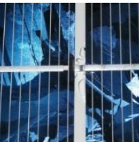
This post provides an overview of interconnection failures in PV modules, explores its failure signatures, apparition times, concomitant failures, and detection techniques.
I. Overview & root causes
In a crystalline silicon PV module, wafer-cells are typically interconnected in series with busbars (or cell interconnect ribbons). These busbars are connected from the front side to the rear side of the solar cells. A series of interconnected cells with a bypass diode in parallel is called a cell string [2]. These cell strings are typically interconnected in series or sometimes in parallel by string interconnect ribbons [2]. The cell interconnections are considered to be both the busbars and string interconnect ribbons.
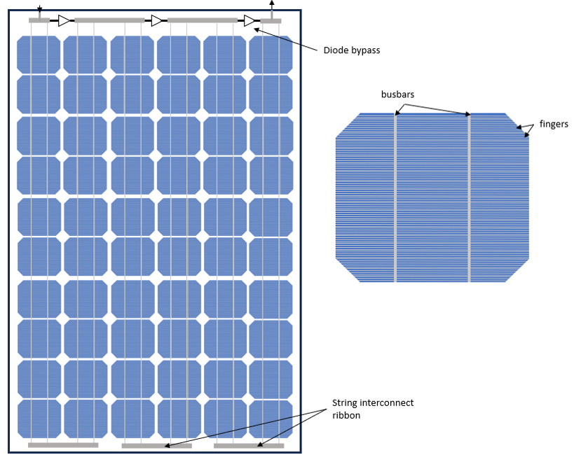
The interconnection failure often come from a combination of reasons at different stages [3]:
- Manufacturing process: poor soldering, misplacement of ribbons, too intense deformation of the ribbon kink, narrow distance between the cells [2], [3], [4]. The lamination process could also facilitate failures [1].
- Transportation: Mechanical stress [2], [4], [5].
- Operation: Thermomechanical stress, repetitive wind load, electrochemical corrosion can also fatigue the interconnections [3]. Hails is also mentioned as a stress [5].
The connection between busbars and string interconnect ribbon is even more subject to fatigue than the rest of the interconnections [2].
II. Signature
If redundant electrical interconnections are available, the failure of one them might have an negligible effect on the overall power output [3]. Nevertheless, if all interconnections of a cell are interrupted so the current flow is blocked, electric arcs might appear if the bypass diode does not operate correctly [3].
Overall, Kontges et al. [2] set up three stages to describe the interconnection failure effects:
- Stage 1: Only a small number of cell interconnections are disconnected. The resistance in series is increased [2], [4] but the current still flows through the cells.
- Stage 2: The cell interconnection ribbons are fully disconnected and the current flows constantly through the bypass diode. At this failure stage, safety risk heavily depends on the durability of this bypass diode [2]. Safety risks are also quite limited while the hot spot temperature does not reach more than 100°C [3].
- Final stage: Safety is at stake where, for instance, the bypass has blown up which results in more damage to the module such as burn marks, glass breakage etc…[2]
In stage 1, the resistance in series seems to be mostly responsible for the power decrease which results in a decrease of fill factor [2], [6]. Colvin et al. particularly highlights that this loss is more severe during more sunny conditions [6]. When having 4 busbars, the power loss per interconnection cut is in the order of 0.1% due to an increase of the resistance in series around 1% [6]. With 3 busbars, the redundancy is decreased and the power loss important around 1%/cut [7]. Both studies [6][7] showed that cutting the outer connections lead to more losses than when cutting the inner connections.
III. Apparition
PV cell interconnection failure occurs over the whole PV installation lifetime. The figure below represents the distribution of the cell interconnection stages over time from a 1080-module system installed in 2004. Note that the first final stages occur 6 years after installation.
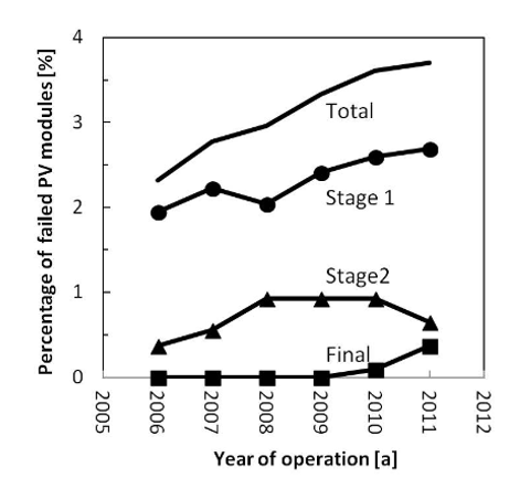
According to Kontges et al. [1], cell interconnection failures seem to appear after 4 years of operating and keep occurring over the whole PV system lifetime.
Bansal et al. [4] emphasize that hot and dry, hot & humid and composite climates might be more prone to cell interconnection failures.
Kontges et al. [2] report that « defect cell interconnect » accounts for 10% of all PV module failures from a pool of customer complaints in the first two years after delivery (2 million PV modules in Germany). In another article, interconnection failure accounts for 3 failures among the 115 module failures from a group of 1-3 year-old modules in USA [8].
IV. Concomitant failures
Several failures usually occur at the same time as interconnection failure.
The corrosion of the cell metallization leads to interconnection fatigue and, potentially, cell interconnection failures [3], [5]. It is usually correlated with a visible light yellow to dark discoloration of the electric parts [3].
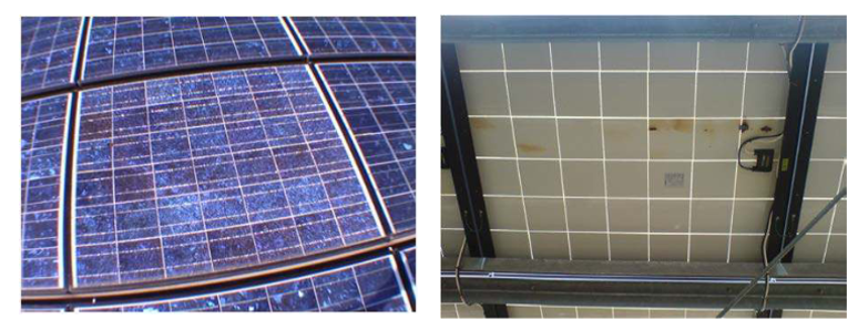
If all interconnection disconnections block the current flow in a cell string, the bypass diode will be activate, and will prematurely age. A failed bypass diode will result in open-circuit or short-circuit state. In case of open-circuited diode, the current will go through the failed cell string and dangerously generate heat which can lead to high temperatures, electric arcs and even fires [3]. Then, in progressed stages, the interconnection failures might cause glass breakage and burn marks [2], [3], [5], [9] as shown in the Figure below.
A defect or detached junction box might also facilitate humidity ingress, resulting in higher corrosion levels with weaker cell interconnections [3].
Hotspots caused from partial shading might accentuate the thermomechanical stress and cause more fatigue on the cell interconnections [2].
V. Detection
Cell interconnection failures are not easy to see with the naked eye [3]. However, burn marks and glass breakage can occur in progressed stages and might reveal them [3].
Infrared images would highlight hotspots caused by interconnect failures [3]. More specifically, poor soldering lead to higher power dissipation and localized heating [3].
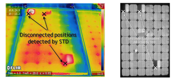
Some other technics are listed to detect interconnection failures [2]:
- Electroluminescence can identify it with darker regions at the failed interconnects [3].
- UV imaging can also detect ribbon breakages [2].
- The signal transmission method is also a cheap method to identify interconnection failures [2].
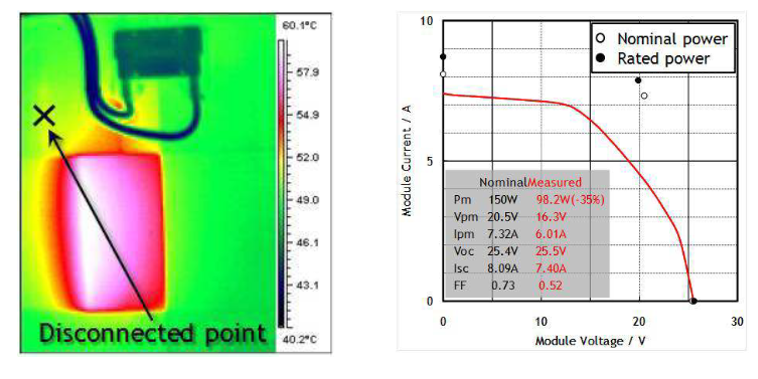
IV curves also enable to detect the performance loss from cell interconnection failures. In the Figure below, the interconnections are redundant, and the interconnection failure causes an increase of the resistance in series with a more “round” knee aspect. It is also combined with some aging effect which decreases the expected photocurrent.
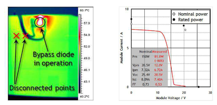
At more advanced stages, the I-V curve can also detect these issues. When multiple interconnection failures block the flow of current, the bypass diode activates, as illustrated in the figure below.
Replacing the module is then advised in advances stages and when burn marks are visible [5].
Finally, interconnection failures might lead to critical performance losses and safety risks. Then, it is crucial to closely monitor PV modules to avoid those situations.
References
[1] M. Köntges, G. Oreski, U. Jahn, M. Herz, P. Hacke, and K.-A. Weiss, ‘Assessment of photovoltaic module failures in the field’, IEA PVPS, IEA-PVPS T13-09:2017, 2017.
[2] M. Köntges et al., ‘Review of Failures of Photovoltaic Modules’, IEA PVPS T13, Technical Report IEA-PVPS T13-01:2014, 2014.
[3] M. Herz, G. Friesen, U. Jahn, M. Köntges, S. Lindig, and D. Moser, ‘Quantification of Technical Risks in PV power Systems’, IEA PVPS, Technical Report IEA-PVPS T13-23:2021, Feb. 2022.
[4] N. Bansal, S. P. Jaiswal, and G. Singh, ‘Comparative investigation of performance evaluation, degradation causes, impact and corrective measures for ground mount and rooftop solar PV plants – A review’, Sustain. Energy Technol. Assess., vol. 47, p. 101526, Oct. 2021, doi: 10.1016/j.seta.2021.101526.
[5] C. Miquel, C. Stravrou, N. Lebert, and J. Sarantou, ‘Dysfonctionnement électriques des installations photovoltaïques: points de vigilance.’, AQC - HESPUL, Technical Report PTVIGI1801, Oct. 2018.
[6] D. J. Colvin, E. J. Schneller, and K. O. Davis, ‘Impact of interconnection failure on photovoltaic module performance’, Prog. Photovolt. Res. Appl., vol. 29, no. 5, pp. 524–532, 2021, doi: 10.1002/pip.3401.
[7] E. Annigoni et al., ‘Quantifying and modeling the impact of interconnection failures on the electrical performance of crystalline silicon photovoltaic modules’, Prog. Photovolt. Res. Appl., vol. 27, no. 5, pp. 424–432, 2019, doi: 10.1002/pip.3111.
[8] S. Deng et al., ‘Research on hot spot risk for high-efficiency solar module’, Energy Procedia, vol. 130, pp. 77–86, 2017, doi: 10.1016/j.egypro.2017.09.399.
[9] E. Sarquis Filho, ‘Toward a Predictive Strategy for the Operation and Maintenance of PV Systems’, PhD Thesis, 2023.
