Junction box failure
Published:
Junction boxes are the connection gates between modules, and their failures can result in substantial performance degradation, safety hazards like internal arcing, and even potential fires.
This blog post provides an overview of junction box failures in PV modules, exploring their root causes, identifying key failure signatures, and outlining effective mitigation strategies.
I. Overview & root causes
The junction box is generally fixed on the back of the PV module and acts as a protection barrier to the internal connections between the terminals and the cell string interconnectors. The junction box also contains the bypass diode which gets activated to protect the PV cells in case of significant mismatches caused from module heterogeneity irradiance conditions or shadow. [1]
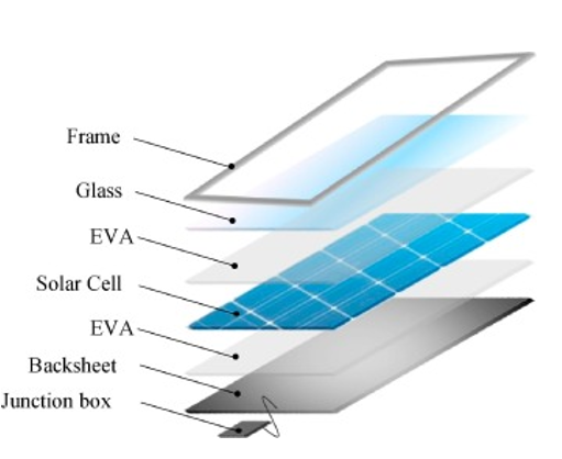
A multitude of defects can occur within the junction box [1], [3], [4]. The box lid can appear weathered, brittle, cracked, warped, melted or burned [4]. The box can also be detached as open or loose. The sealing components might be compromised (squeezed, broken, brittle) or even completely missing [4].
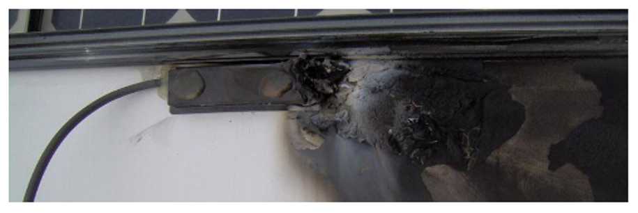
According to Kontges et al. [1], observed failures can be categorized as follows (non-exclusive categories).
- Poor adhesion of the junction box to the backsheet. Junction box detachment results from poor fixing of the junction box to the backsheet or use of low quality adhesive [4].
- Opened or badly closed j-boxes due to poor manufacturing process or air pressure caused by high temperature for boxes with no exhaust path [4].
- Moisture ingress which cause corrosion of the connections and the cell string interconnectors [1], [4].
- Internal arcs in the j-box which can potentially initiate fire. Bad soldering contacts are caused by low temperatures or chemical residuals during the soldering process [1], [4].
More specifically, inadequate IP rating junction box may cause water intrusion and subsequent failure [4].
Improper mounting of PV modules can be also the cause of damaged the j-box with the wrong adjustment of cabling sizes to interconnect modules to a string, causing mechanical stress on the j-boxes [4].
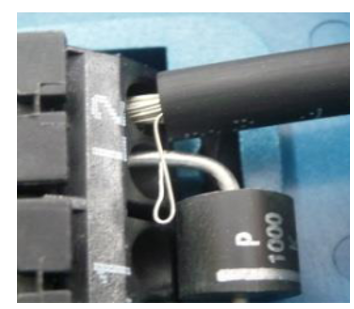
Mechanical contacts can also get loose due to the thermal cycling of day and night and seasonal changes [4].
Chang et al. [6] report 85% of the junction box faults to be caused by the system installation, 8% from the manufacturing and 7% from the junction box supplier when investigating 1250 project sites worldwide. Energy over stress is mentioned as the main root cause [6].
II. Apparition rate
The junction box is frequently mentioned in field reliability reports, though it is often grouped with another category. For instance, Kontges et al. [1], reports that “junction box and cable” failures account for 19% and 12% of all failures from customer complaints (Germany, 2 million PV modules) and field data (21 manufacturers, 8-year-old modules). Golnas reports that junction boxes are responsible for 6% of the PV module tickets over 350 PV systems operated by SunEdison [7]. Wohlgemuth reports that junction box accounts for 3.8% of all observed failures from 1994 through 2005 at BP Solar and Solarex [5]. From a literature review, Sarquis Filho [8] reports junction box failure to account for no more than 2% of all failures.
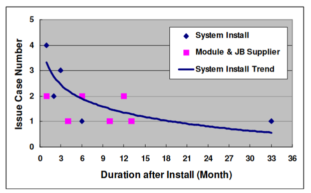
According to Collins et al. [9], the failure distribution for the RowBox (considered as a junction box) indicates a slightly higher likelihood of failure in the initial years for a 4.6 MW PV silicon system in Arizona, but this probability stays relatively constant throughout the remaining lifespan of the PV module. Chang et al. [6] further accentuate this “infant” failure characteristic stating that 85% of the failures are included within the first three months after commissioning as seen in the Figure below.
III. Signature & concomitant failures
Bad contacts or corrosion can increase the internal resistance and, consequently, heating the junction box [1], [4], [8].
In the worst case junction box failures cause interconnection failure (module or cell strings short-circuited or open-circuited) or internal arcing within the j-box [4]. Insulation faults are also part of the listed consequences from junction box failures [10].
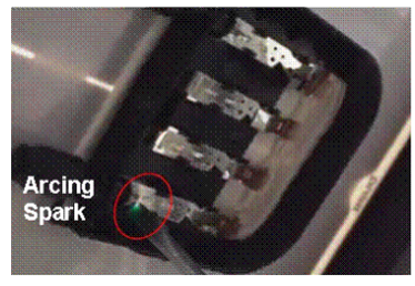
Several anomalies usually occur at the same time as junction box failure.
- Localized more discolored cells due to encapsulant degradation or burn marks might be above the junction box which has higher temperatures than the rest of the module [4].
- Delamination near the junction box might induce water ingress which can enhance junction box corrosion or even insulation fault with serious safety concerns during humid periods [4]. Also, delamination can cause the junction box to be loose which result in a mechanical stress on its internal components like bypass diodes or connectors which might lead to electrical arcs in some cases [4].
- Bypass diode failures sometimes cause the junction box to deform or even burnt due to the heat dissipation [4], [10].
- Mounting structure failures might lead to junction box failures in some cases [4].
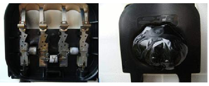
According to Bansal et al. [10], hot climate might accelerate junction box failures.
IV. Mitigation
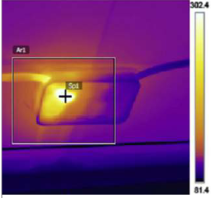
Several inspection method enable to detect junction box failures. Monitoring tools might detect a loss in performance in case of short-circuit or open-circuit configurations from the junction box failures [11]. Then, visual inspection is the common way to identify junction box failures [4], [11].Higher resistive effects in the junction box or mismatches can be detected with an infrared camera [4], [11].
In the case of interconnection failures, short-circuits can be detected with the open-circuit measurement (or IV curve) [4].
If a junction box fail, it is advised to replace the module, since repairing junction boxes might easily lead to new fires [11].
Chang et al. [6] provide several recommendations at different levels:
- System installation: installing suitable protection devices (lighting protector, string diode etc…) would help to prevent energy over stress which is one main identified root cause. Employing qualified constructors, making sure of the string polarity and avoiding un-authorized rework for cable and connectors would facilitate better reliability [6].
- Module manufacturing: improving the quality of the fabrication process with trained operators is recommended as well as putting a focus on junction reliability in their process [6]. Proper lamination would also reduce water ingress likelihood and the progress of corrosion [10].
- Junction box supplier: automatic inspection systems and refining design rules to improve reliability is advised to junction box suppliers [6]. Proper junction box sealing would also limit failures [10].
The IEC 62790 standard particularly sets design and testing requirements for junction boxes used in photovoltaic (PV) modules, focusing on safety and durability. Key design criteria include a minimum IP55 protection rating, operational temperatures from -40°C to +85°C, and safety classifications. The standard outlines tests for material durability (such as corrosion, aging…) and electrical safety (including insulation, terminal connections, and mechanical safety). Among the identified gaps for the IEC 62790 standard mentioned in the literature [11], it does not provide guidance for certification when components are changed, leaving it to manufacturers or laboratories. Also, most module datasheets mention protection ratings and safety class but often omit compliance with the standard.
Ultimately, understanding the root causes and implementing preventive measures is vital to reducing the risk of junction box failures and ensuring long-term PV system reliability.
Reference
[1] M. Köntges et al., ‘Review of Failures of Photovoltaic Modules’, IEA PVPS T13, Technical Report IEA-PVPS T13-01:2014, 2014.
[2] F. C. S. M. Padoan, P. Altimari, and F. Pagnanelli, ‘Recycling of end of life photovoltaic panels: A chemical prospective on process development’, Sol. Energy, vol. 177, pp. 746–761, 2019, doi: 10.1016/j.solener.2018.12.003.
[3] M. Köntges, G. Oreski, U. Jahn, M. Herz, P. Hacke, and K.-A. Weiss, ‘Assessment of photovoltaic module failures in the field’, IEA PVPS, IEA-PVPS T13-09:2017, 2017.
[4] M. Herz, G. Friesen, U. Jahn, M. Köntges, S. Lindig, and D. Moser, ‘Quantification of Technical Risks in PV power Systems’, IEA PVPS, Technical Report IEA-PVPS T13-23:2021, Feb. 2022.
[5] J. H. Wohlgemuth, ‘Reliability of PV systems’, Reliab. Photovolt. Cells Modul. Compon. Syst., vol. 7048, pp. 11–23, 2008, doi: 10.1117/12.795248.
[6] M. Chang et al., ‘The reliability investigation of PV junction box based on 1GW worldwide field database’, in 2015 IEEE 42nd Photovoltaic Specialist Conference (PVSC), 2015, pp. 1–4. doi: 10.1109/PVSC.2015.7356130.
[7] A. Golnas, ‘PV system reliability: An operator’s perspective’, in 2012 IEEE 38th Photovoltaic Specialists Conference (PVSC) PART 2, 2012, pp. 1–6. doi: 10.1109/PVSC-Vol2.2012.6656744.
[8] E. Sarquis Filho, ‘Toward a Predictive Strategy for the Operation and Maintenance of PV Systems’, PhD Thesis, 2023.
[9] E. Collins, M. Dvorack, J. Mahn, M. Mundt, and M. Quintana, ‘Reliability and availability analysis of a fielded photovoltaic system’, in IEEE Photovoltaic Specialists Conference (PVSC), 2009, pp. 002316–002321. doi: 10.1109/PVSC.2009.5411343.
[10] N. Bansal, S. P. Jaiswal, and G. Singh, ‘Comparative investigation of performance evaluation, degradation causes, impact and corrective measures for ground mount and rooftop solar PV plants – A review’, Sustain. Energy Technol. Assess., vol. 47, p. 101526, Oct. 2021, doi: 10.1016/j.seta.2021.101526.
[11] C. Miquel, C. Stravrou, N. Lebert, and J. Sarantou, ‘Dysfonctionnement électriques des installations photovoltaïques: points de vigilance.’, AQC - HESPUL, Technical Report PTVIGI1801, Oct. 2018.
[12] H. E. Yang, R. French, and L. Bruckman, Durability and reliability of polymers and other materials in photovoltaic modules. William Andrew, 2019.
