Connector defect
Published:
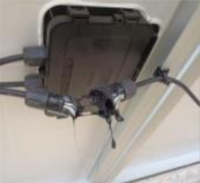
Connectors are widely used throughout PV systems and electrically connect PV modules to each other, to combiner boxes, fuse boxes or inverters [1]. Nevertheless, connector failures can lead to dramatic consequences such as open-circuits, insulation faults, electrical risks and, even fire.
This blog post investigates the causes, the apparition time and signature of the connector failures.
I. Causes
The most common connectors are MC4 which can be connected by hand but needs to be disconnected with a tool for safety purposes.

A weak connection can lead to ground-fault, arcing and fires [2] and a significant share of PV fire sources come from quick connector defects [1]. Connector failures come typically from forcing different types of connectors to connect or not-well crimped connectors [1]. Even if aging mechanisms with corrosion due to long exposure to weather with UV and humidity are identified for connectors, failures are most likely to be related to installation issues [3]. Improper installations, mismatch connectors, low-quality and faulty materials are the common root causes of connector failures [4].
II. Time apparition
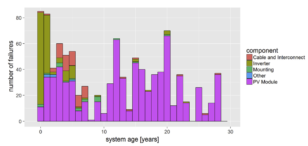
Connector failures mostly occur during the first years after commissioning [2], [5] However, two reports [2], [6] show that most of the failures do not happen directly on the first year after the installation but rather several years after as shown with the generic “cable and interconnect” failure category in the figure below.

From a statistic perspective, Jordan et al. [7] shows that there is connector failure for 0.002 - 0.035 % out of the 100 000 studied systems in USA per year. Also, Baschel et al. [8] outline from O&M reports, where no information is disclosed on the PV installations due to confidentiality agreement, a failure rate of $5.6 \cdot 10^{-9} failures/hour$. Another report [9] highlights a share of 6% for connectors among all PV module failures from more than 600 PV systems over several continents.
III. Signature
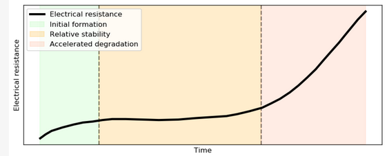
The contact resistance observes three stages according to the IEC 61238-1-1 standard [10] as shown in the figure below. The initial stages see resistance change as stable areas form after connector installation, followed by a stable phase. Those two stages are included in the expected PV system degradation over time. In the final accelerated aging stage, resistance very quickly increases as the connector nears its end of life. This evolution over time can also be described as exponential [11].

Failed connectors usually go through two phases. The first phase can be modeled with an increase a resistance in serie with a thermal dissipation that can be identified with thermographies [3], [4]. However, this resistance increase might be too small to detect, electrically-wise and visually-wise. Sometimes there is a transitional period towards the second phase which consists in low insulation faults which might be intermittent due to varying environment conditions with, for instance, different levels of humidity modifying the conductivity. The second phase corresponds to a complete compromised connector. It is usually characterized either by a ground fault or a burst connector which opens the string circuit.
Infrared images detect early symptoms while visual inspection enables to quickly scan connector defects.
Connector failures in PV systems, often due to poor installation or mismatched components, can lead to serious electrical hazards, emphasizing the need for proper installation and regular maintenance to prevent long-term damage and risks.
References
[1] M. Köntges et al., ‘Review of Failures of Photovoltaic Modules’, IEA PVPS T13, Technical Report IEA-PVPS T13-01:2014, 2014.
[2] L. Burnham et al., ‘Connector Reliability Across the U.S. Solar Sector’, in Report Number: NREL/PR-7A40-87751, Research Org.: National Renewable Energy Laboratory (NREL), Golden, CO (United States), Jan. 2024.
[3] E. Sarquis Filho, ‘Toward a Predictive Strategy for the Operation and Maintenance of PV Systems’, PhD Thesis, 2023.
[4] Todd Karin, David Penalva, and James Nagel, ‘The Ultimate Safety Guide for Solar PV Connectors’, Heliovolta, 2022.
[5] Urs Muntwyler, ‘New Findings in Fire Prevention and Fire Fighting of PV Installations’, Munich, Germany, 2016.
[6] M. Halwachs et al., ‘Statistical evaluation of PV system performance and failure data among different climate zones’, Renew. Energy, vol. 139, pp. 1040–1060, 2019, doi: 10.1016/j.renene.2019.02.135.
[7] D. C. Jordan, B. Marion, C. Deline, T. Barnes, and M. Bolinger, ‘PV field reliability status—Analysis of 100 000 solar systems’, Prog. Photovolt. Res. Appl., vol. 28, no. 8, pp. 739–754, 2020, doi: 10.1002/pip.3262.
[8] S. Baschel, E. Koubli, J. Roy, and R. Gottschalg, ‘Impact of Component Reliability on Large Scale Photovoltaic Systems’ Performance’, Energies, vol. 11, no. 6, 2018, doi: 10.3390/en11061579.
[9] A. Golnas, ‘PV system reliability: An operator’s perspective’, in 2012 IEEE 38th Photovoltaic Specialists Conference (PVSC) PART 2, 2012, pp. 1–6. doi: 10.1109/PVSC-Vol2.2012.6656744.
[10] IEC, ‘IEC 61238-1-1:2018 Compression and mechanical connectors for power cables’. May 2018.
[11] J.-R. Riba, Á. Gómez-Pau, J. Martínez, and M. Moreno-Eguilaz, ‘On-Line Remaining Useful Life Estimation of Power Connectors Focused on Predictive Maintenance’, Sensors, vol. 21, no. 11, 2021, doi: 10.3390/s21113739.
